A Moiré pattern is the interference pattern that emerges when you superimpose two grids that nearly line up. For instance, you could have two identical metal sheets with circular holes. If you put one in front of the other, and slightly rotate it, then you get a Moiré pattern.
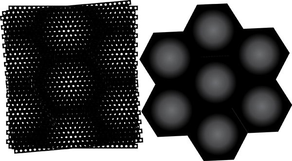
Left: a Moiré pattern formed by two hexagonal grids of circular holes, one rotated by 5 degrees. Right: an artist’s (my) conception of the resulting Moiré pattern. This and all other images were drawn “by hand” (with Illustrator), so please accept some imperfection.
A reader expressed curiosity about what would happen if you replaced the circles with a different shape. As it happens, I am a former condensed matter physicist, which makes me a sort of expert in lattices. So I already know the answer, but let me walk you through with illustrations.
Here’s a second example of a Moiré pattern. This one uses two hexagonal grids of square holes. One grid is 10% larger than the other. (In general Moiré patterns can be formed by all sorts of distortions, but in this article, I stick to slight rotations and slight size adjustments). Something you might notice is that the Moiré pattern has a definite square-ness to it.
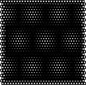
A Moiré pattern formed by two hexagonal grids of square holes, one 10% larger than the other.
So far we have…
Circular hole -> Circular Moiré pattern
Square hole -> Square Moiré pattern
Can we extrapolate, and say that a cat-shaped hole will produce a cat-shaped Moiré pattern, or that an Eiffel-Tower-shaped hole will produce an Eiffel-Tower-shaped Moiré pattern? Unfortunately not. I will illustrate this with the simplest shape possible, an L. Here’s what the Moiré pattern looks like.
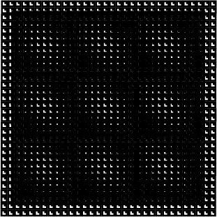
A Moiré pattern formed by two square grids of L-shaped holes, one 10% larger than the other.
The Moiré pattern definitely has a shape, something like a diagonal barbell. But it is definitely not the same L-shape as the holes.
What you’re looking at is the autocorrelation function of the L shape. The autocorrelation function is equal to the area of the overlap between two L shapes, when one is shifted relative to the other. The center of the Moiré pattern corresponds to a shift of zero. If one grid is made larger than the other grid, then the left and right sides of the Moiré pattern correspond to a horizontal shift. The top and bottom of the Moiré pattern correspondes to a vertical shift, and so on. I illustrate this in the image below.
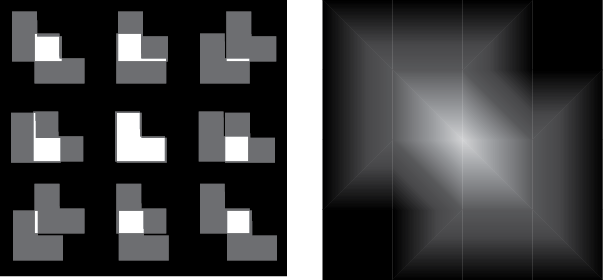
Left: Showing the degree of overlap between two L-shaped holes for different amounts of shift. Right: A very rough sketch of the autocorrelation function.
If instead of making one grid larger than the other, we rotate the grids relative to each other, then the Moiré pattern consists of the autocorrelation function rotated by 90 degrees.
Unfortunately, autocorrelation functions cannot be used to make arbitrary shapes. For one thing, autocorrelation functions have 180 degree rotational symmetry. So, no cat-shaped patterns.
Unless! You use differently shaped holes for the two grids. For instance, one grid can be made from circular holes, and the other from cat-shaped holes. The Moiré pattern will not look like the autocorrelation between a shape and itself, but instead look like the correlation between the two shapes. I tried it out, and it works!
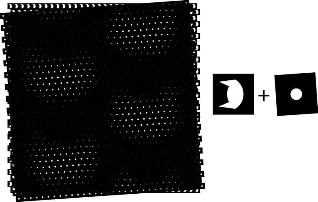
A Moiré pattern formed from overlapping a grid of cat-shaped holes with a grid of circular holes. The two grids are rotated 4 degrees apart. Note that since I use rotation rather than resizing, the Moiré pattern is equal to the correlation function rotated by 90 degrees. Click for bigger image.
I can readily see how a beat-type pattern arises from superimposing two patterns of slightly different scale, but how the same sort of thing arises from a slight rotation between two identical patterns is, er, a bit more opaque to me. I might waste some time thinking about it.
@Rob,
Here’s how I was thinking about it. We have two lattices A and B, where B is distorted relative to A. Some distortions such as rotation or scaling can be represented by a linear transformation M. So we have B = MA.
Next we consider a particular point x in lattice A. The corresponding point in B is at Mx. The displacement between the two points is Mx – x. Put another way, it’s (M-I)x. So at any position x, the average brightness of the Moiré pattern is f((M-I)x), where f is the autocorrelation function. So the Moiré pattern is going to look like a linear transformation ((M-I)^-1 to be precise) of the autocorrelation function.
If M is a scaling transformation, then (M-I)^-1 is also a scaling transformation. If M is a small-degree rotation, then (M-I)^-1 is a scaling transformation plus 90 degree rotation.
Cool! My take-away is that rando drive-by comments pay off sometimes. I will have to take a close look at this.
Even if it is not the obvious magnification I was thinking it would be, there are definitely a lot of opportunities for art in public spaces. I wonder if anyone has explored the potential. I often notice it more more less fortuitously, where the sheet metal is there but I don’t think the Moiré pattern is intentional.
Do you really have to rotate? Isn’t it sufficient to place them some distance apart?
@PaulBC
No, you don’t have to rotate. Either scaling or rotating works fine. If you have two lattices some distance apart, the parallax makes it look like one is scaled compared to the other.
Siggy @2:
Ahah! Got it, thanks.
Siggy@5 When I first thought about analyzing this, I considered writing program to do simple ray tracing through pairs of holes in displaced sheets. It wasn’t something I had time for so I put it out of my mind. Now I realize that I can just use a transparent PNG with a periodic pattern and superimpose it with a scaled down copy of itself.
I feel very silly for not thinking of that now. I might try it today in fact.
This is absurdly simple (compared to my original thoughts) and I did it in a couple of minutes by searching for a black square png, opening it up in Mac preview, using cut and paste to remove an interior square, then inserting the png into a Google doc, making a periodic pattern with copy-paste and then scaling one copy to 90%. I hope doc links are OK. This is public but view-only. https://docs.google.com/drawings/d/1akmaEf0FZk95jcuU02A6h95u4nC9Z4mU3bNf6cK8Enk/edit?usp=sharing
It would be fairly easy to construct other grids with different placements and hole shapes using a script.
@PaulBC,
Yeah, that’s more or less the same process I was using, but with different software (I’m using Adobe Illustrator). I just made a square with a shape cut out, then I copy/pasted it a bunch of times, doubling the number of squares at each step. I’ve actually used this process plenty of times before to draw origami tessellation crease patterns. Most of these aren’t public, but here’s one example. And of course, I used the same process last time I generated Moire patterns.
There’s also another way to do it using Illustrator’s “pattern” tool, but I haven’t tried it yet. Maybe that would be easier. I can try that next time.
I do feel like someone should just make an interactive webapp for Moire patterns. It’s a project for a web developer.
I reacquainted myself with imagemagick to take some of the manual work out of this. It’s free and easy to install. (https://imagemagick.org/)
Here’s script that produces the final image of a crude cat-head-shaped polygon.
# make the upside down "cat" polygon and square with a square pinholeconvert -size 100x100 xc:none -fill black -stroke none -draw "path 'M 0,0 0,100 100,100 100,0 Z M 15,25 50,10 85,25 85,60 70,85 55,60 45,60 30,85 15,60 Z' " cat.png
convert -size 100x100 xc:none -fill black -stroke none -draw "path 'M 0,0 0,100 100,100 100,0 Z M 45,45 55,45 55,55 45,55 Z' " pinhole.png
# scale down the pinhole to 95%
convert pinhole.png -resize 95x95 pinhole2.png
# tile the images into periodic grids
convert -size 3200x3200 tile:cat.png grid1.png
convert -size 3200x3200 tile:pinhole2.png grid2.png
# superimpose them into a moire patten
convert grid1.png grid2.png -layers flatten moire.png
…and a link to the generated images. https://drive.google.com/drive/folders/1BFubUAK6-5BPL1tSwwiyk5m2RjWR_LWg?usp=sharing
So my intuition wasn’t totally off, but your point about autocorrelation is well taken. In fact, the second grid produces the sharpest image if it consists of pinholes that are small compared to the image being magnified (and like a normal pinhole camera, you trade off in the amount of light coming through).
I bet this would make a good outdoor display that people have not seen before (with a more interesting image).
The magnification will change with distance from the display. E.g. at 19 feet from the near sheet, its spacing will appear to be 20/19 that of the far sheet (or am I off by a little?). Does the magnification compensate for distance so the image appears the same size? (Lazy question. I should work it out.)
(That’s the Moiré cat. Now if I could just draw a recognizable eel.)
Small update: I now see that if I had scaled up the pinhole grid by 5% instead of down, I would not have to contend with upside down images. So if the pinholes are the nearer sheet, you want the image grid to be right side up. In principle I guess the viewer could be on either side, so maybe it is not worth worrying too much. I wonder how much it costs to get these kinds of sheets fabricated.