Parallel link robot

Inactive Publication Date: 2013-08-15
YASKAWA DENKI KK
View PDF6 Cites 6 Cited by
  • Summary
  • Abstract
  • Description
  • Claims
  • Application Information

AI Technical Summary

Benefits of technology

[0011]In the parallel link robot in accordance with one aspect of the present invention, the biasing mechanism unit is configured to include the first connection member attached to the second arm. The first connection member is configured to include the first locking portion arranged to lock the first connection member to the second arm. Accordingly, the first connection member can be locked to the second arm by the first locking portion, and the biasing mechanism unit can be attached to the second arm by the first connection member locked to the second arm. Therefore, even if the first joint portion o

Problems solved by technology

This poses a problem in that the bias

Method used

View more

Image

Smart Image Click on the blue labels to locate them in the text.
Viewing Examples
Smart Image
  • Parallel link robot
  • Parallel link robot
  • Parallel link robot

Examples

Experimental program
Comparison scheme
Effect test

first embodiment

[0025]Referring to FIGS. 1 through 6, description will be made on the configuration of a parallel link robot 100 in accordance with a first embodiment of the present invention.

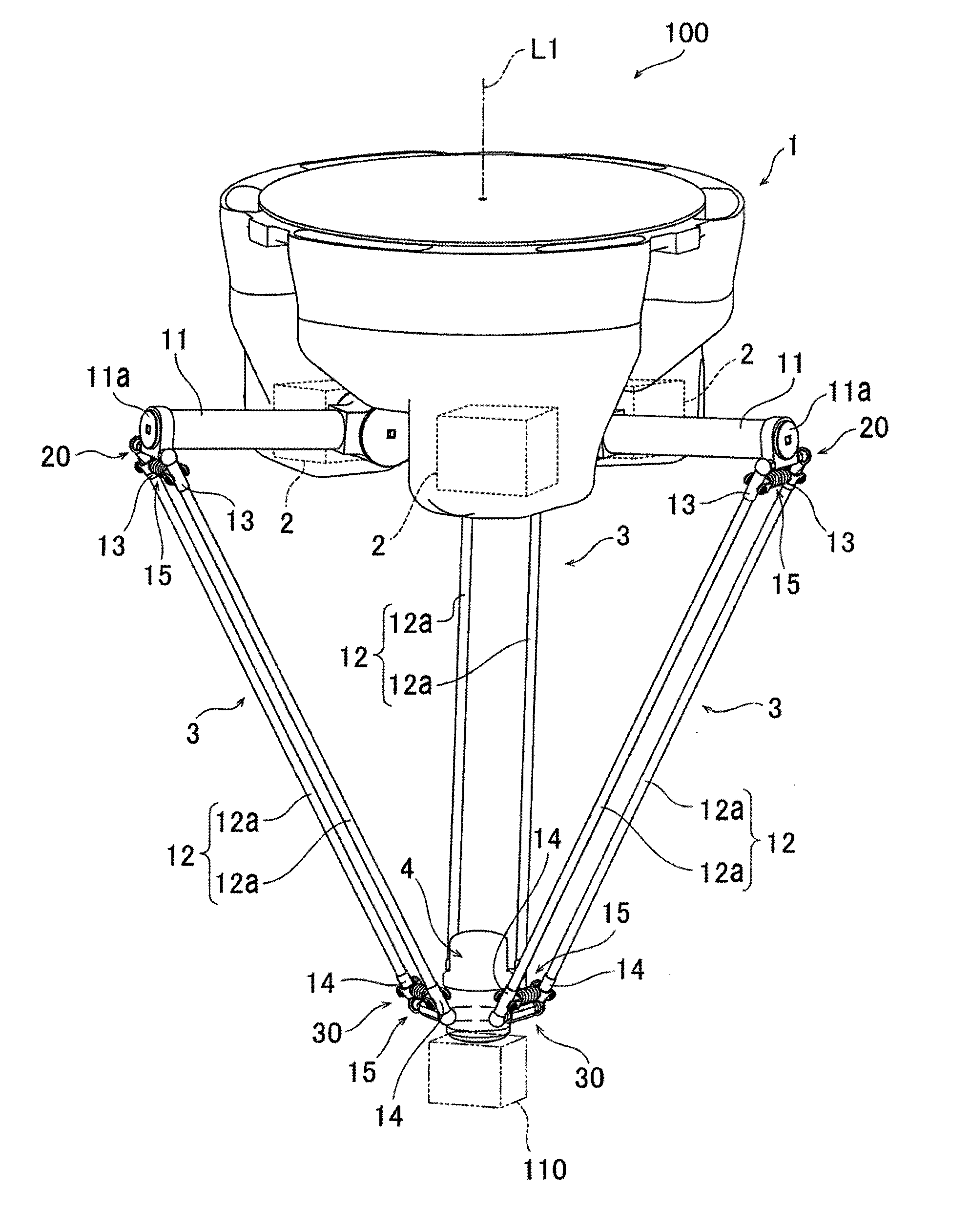
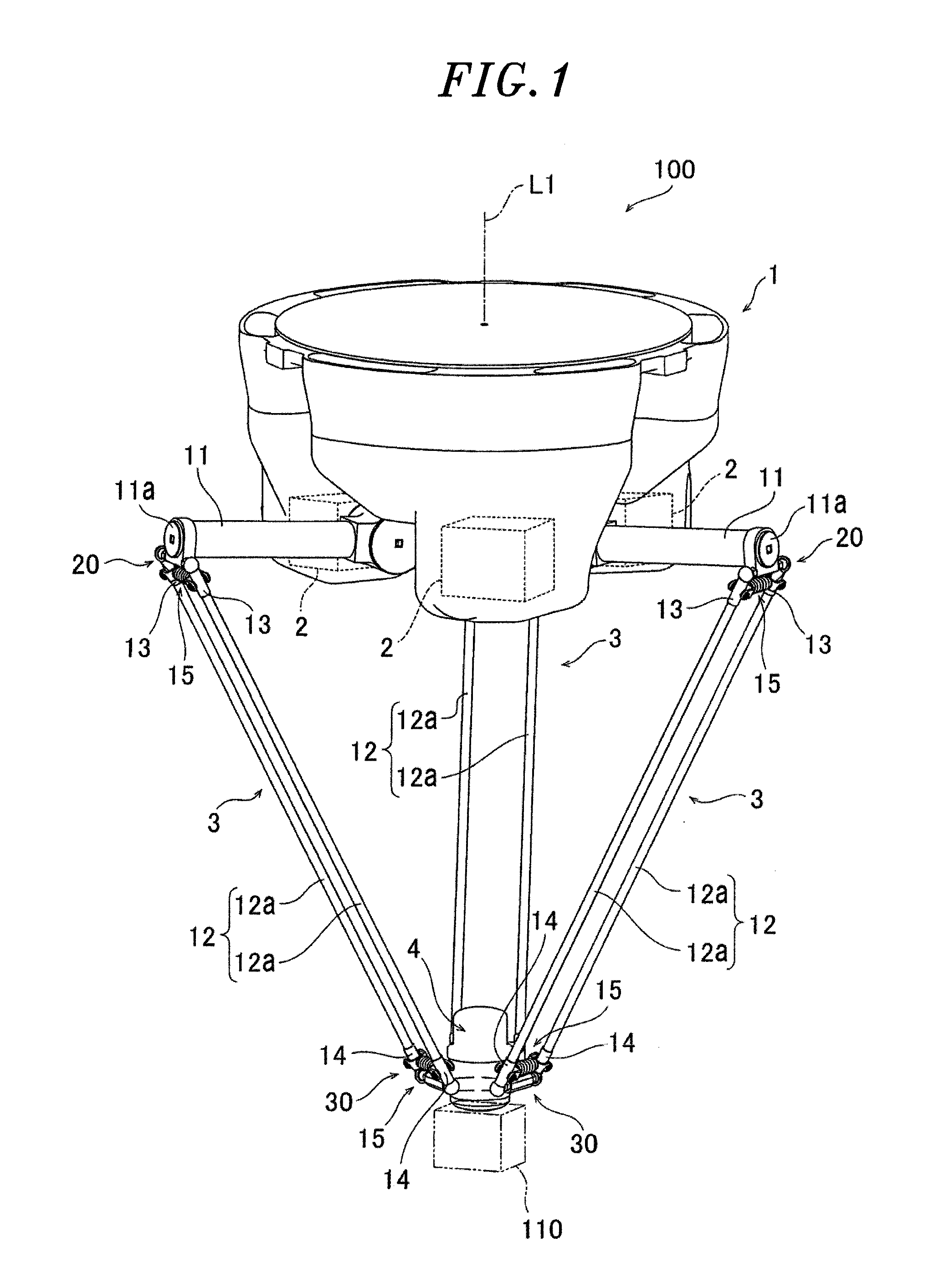
[0026]As shown in FIG. 1, the parallel link robot 100 in accordance with the first embodiment includes a base unit 1, three servo motors 2 arranged in the base unit 1, three arm units 3 respectively driven by the three servo motors 2, and a head unit 4 to which an end effecter 110 is attached.

[0027]The base unit 1 is attached to a fixing surface of a ceiling or the like. The three servo motors 2 are arranged within the base unit 1. When seen in a plan view, the three servo motors 2 and the three arm units 3 are arranged at an equal angular interval (at an interval of 120 degrees) around the center axis L1 of the base unit 1 extending in the vertical direction.

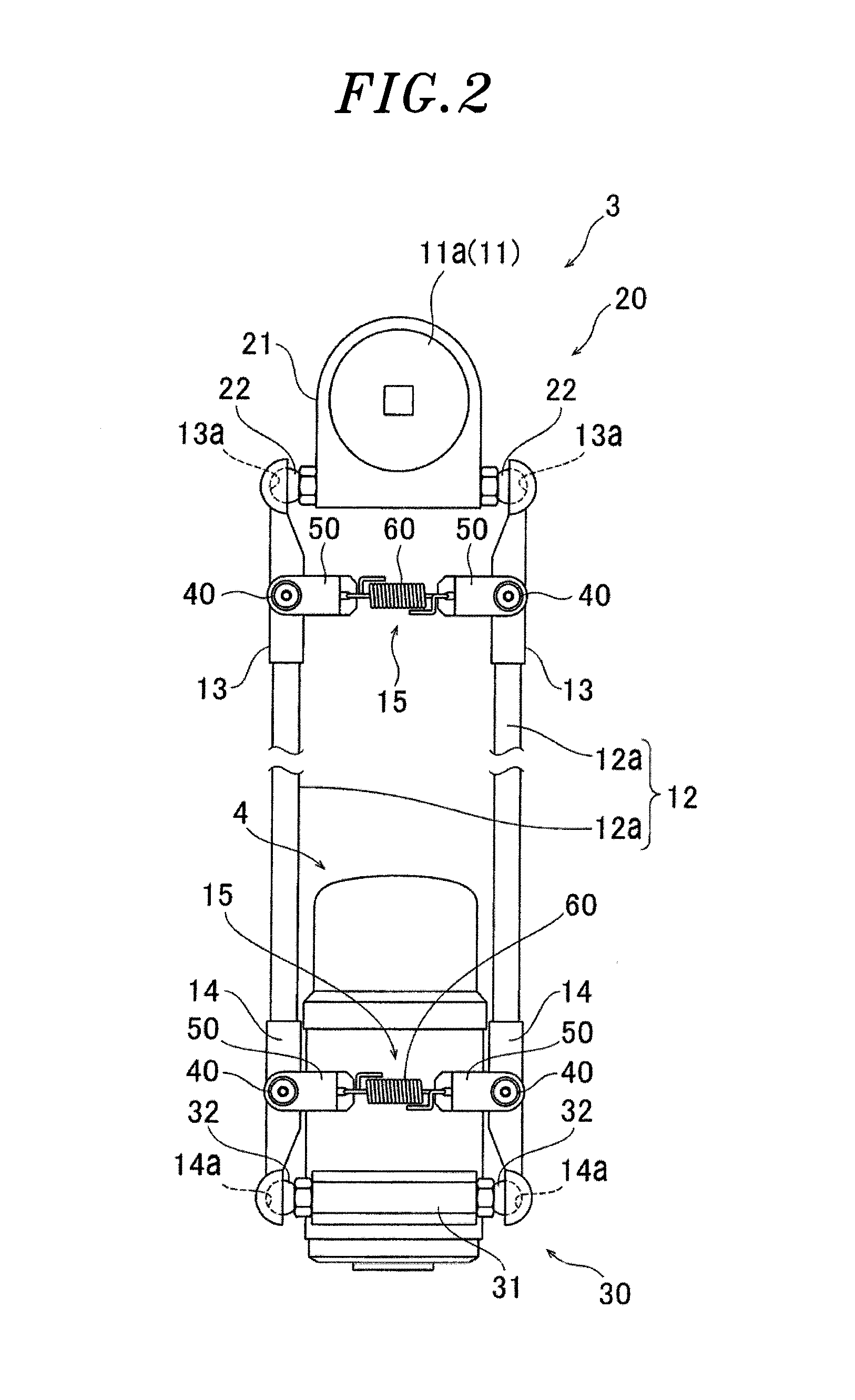
[0028]The three arm units 3 are identical in configuration with one another. More specifically, each of the arm units 3 includes an upper arm 11 and a lo...

second embodiment

[0064]Next, a second embodiment of the present invention will be described with reference to FIGS. 8 through 10. In the second embodiment, description will be made on the configuration of a biasing mechanism unit 115 differing from the biasing mechanism unit 15 of the first embodiment. Other configurations than the biasing mechanism unit 115 are the same as those of the first embodiment and, therefore, will not be described herein. In the biasing mechanism unit 115, the same portions as those of the first embodiment will be designated by like reference symbols with no description made thereon.

[0065]In the second embodiment, as shown in FIGS. 8 and 10, large diameter portions 141 having a large outer diameter D10 are formed in the axial opposite side regions of the outer circumferential surface of each of the first connection members 140. A small diameter portion 142 having a small diameter D9 smaller in diameter than the large diameter portions 141 is formed in the axial central reg...

Login to view more

PUM

No PUM Login to view more

Abstract

A parallel link robot includes a first arm including a first joint portion; a second arm including a second joint portion swingably engaging with the first joint portion, the second arm being connected to the first arm to make up a link mechanism; and a biasing mechanism unit which biases the second joint portion toward the first joint portion. The biasing mechanism unit includes a connection member attached to the second arm and the connection member includes a locking portion configured to lock the connection member to the second arm.

Description

CROSS-REFERENCE TO RELATED APPLICATION[0001]The present disclosure contains subject matter related to that disclosed in Japanese Priority Patent Application No. 2012-022026 filed on Feb. 3, 2012. The contents of this application are incorporated herein by reference in their entirety.BACKGROUND OF THE INVENTION[0002]1. Field of the Invention[0003]The present invention relates to a parallel link robot and, more particularly, to a parallel link robot having joint portions.[0004]2. Description of the Related Art[0005]In the past, there is known a parallel link robot that includes a plurality of arms arranged side by side and capable of being bent and stretched in joint portions (see, e.g., Japanese Patent Application Publication No. 2011-194534).[0006]JP2011-194534A discloses a parallel link robot including a first arm having a first joint portion, a second arm having a second joint portion engaging with a first engagement portion, and a biasing mechanism unit for biasing the second joi...

Claims

Login to view more

Application Information

Patent Timeline
no application Login to view more
IPC IPC(8): B25J18/00
CPCB25J17/0266B25J9/003Y10T74/20305Y10S901/27B25J9/0051B25J18/00
Inventor FUKUDOME, KAZUHIROMIHARA, NOBUHIKO
Owner YASKAWA DENKI KK
Who we serve
  • R&D Engineer
  • R&D Manager
  • IP Professional
Why Eureka
  • Industry Leading Data Capabilities
  • Powerful AI technology
  • Patent DNA Extraction
Social media
Try Eureka
PatSnap group products