FIELD OF THE INVENTION
The present invention relates to a method of estimating a transmission or telecommunications channel which uses complementary sequences. The method results in an optimal estimation of the delays, phases and attenuations of the different paths in the case of a single-path or multipath channel.
BACKGROUND OF THE INVENTION
In a telecommunications system, information circulates between transmitters and receivers through channels. In this connection, FIG. 1 illustrates a model, which is discrete in time, of the transmission chain between a transmitter 1 and a receiver 2 through a transmission channel 3. As a general rule, the transmission channels can correspond to different physical, radio, wire, optical media etc., and to different environments, fixed or mobile communications, satellites, submarine cables, etc.
As a result of the multiple reflections of which the waves emitted by transmitter 1 can be the object, channel 3 is a multipath channel which is generally modelled as FIG. 1 indicates. It is then considered to be a shift register 30 comprising L serial cells (referred to by a subscript k able to take values of between 1 and L) and the contents of which slide towards the right of FIG. 1 each time a symbol arrives at its input. The output of each cell with the subscript k is applied to a filter 31 representing the interference undergone by this output and introducing an attenuation of the amplitude αk, a phase shift αk and a delay rk. The outputs of the filters are summed in a summer 32. The total impulse response thus obtained is marked h(n).
The output of summer 32 is applied to the input of an adder 33 for the addition of a random signal, modelled by a Gaussian white noise, w(n) which corresponds to the thermal noise present in the telecommunications system.
In FIG. 1, the reference h(n) has been used, in channel 3, for the register 30, the filters 31 and the summer 32, followed by an adder 33 which adds the noise w(n).
It will be understood that, if the transmitter
1 transmits the signal e(n), the signal received r(n), in the
receiver 2, is thus:
In these expressions
denotes the impulse response of the channel, δ(n) being the Dirac impulse and δ(n−r
k) denoting a delay function of the value r
k. The operator * denotes the convolution product, defined by the following relation:
Thus it is generally necessary to determine the characteristics of channel 3, at a given moment, in order to thwart the induced distortion of the transmitted signal e(n). In order to obtain an estimation of h(n), i.e. of the coefficients αk, rk and αk of the model of channel 3, it is necessary to repeat this operation at a greater or lesser frequency depending on the rate at which the characteristics of the channel evolve.
A widespread method of estimating the channel consists in transmitting, via transmitter
1, signals e(n) which are predetermined and known to
receiver 2, and in comparing the signals received r(n) in
receiver 2, by means of a periodic or aperiodic correlation, with those which are expected there in order to deduce from them the characteristics of the channel. The aperiodic correlation of two signals of length N has a total length 2N−1 and is expressed, from the convolution product, by the relation:
for two signals a(n) and b(n) of finite length N, where the operator * denotes the complex conjugate operation.
The correlation of the received signal r(n) with the known transmitted signal e(n) translates as:
The result of the correlation operation constitutes the estimation of the impulse response of the channel: the quality or the precision of the estimation is all the better if Φe,r(n) tends towards h(n). The latter is directly dependant on the choice of transmitted sequence e(n); to optimise the estimation process, the signal e(n) should be chosen in such a way that the auto-correlation Φe,e(n) tends towards k·δ(n), k being a real number, and that Φe,w(n)/Φe,e(n) tends towards 0. In fact, in this case, the estimation of the channel becomes:
Φe,r(n)=k·δ(n)*h(n)+Φe,w(n)=k·h(n)+Φe,w(n)
Φe,r(n)≈k·h(n)
It has been demonstrated that no single sequence exists for which the function of aperiodic auto-correlation Φe,e(n)=k·δ(n).
One object of the present invention consists in using pairs of complementary sequences which have the property that the sum of their auto-correlations is a perfect Dirac function. Let s(n) and g(n), n=0, 1, . . . N−1 be a pair of complementary sequences:
Φs,s(n)+Φg,g(n)=k·δ(n) (1)
Several methods of constructing such complementary sequences are known in the literature: Golay complementary sequences, polyphase complementary sequences, Welti sequences, etc. By way of information, one will be able to refer, in this connection, to the following technical documents which deal with the introduction to complementary sequences and, in particular, to Golay complementary sequences as well as to a Golay correlator:
1) “On aperiodic and periodic complementary sequences” by Feng K., Shiue P. J. -S., and Xiang Q., published in the technical journal IEEE Transactions on Information Theory, Vol. 45, no. 1, January 1999,
2) “Korrelationssignale” by Lüke H. -D, published in the technical journal ISBN 3-540-54579-4, Springer-Verlag Heidelberg New York, 1992,
3) “Polyphase Complementary Codes” by R. L. Frank, published in the technical journal IEEE Transactions on Information Theory, November 1980, Vol. IT26, no. 6,
4) “Multiphase Complementary Codes” by R. Sivaswamy, published in the technical journal IEEE Transactions on Information Theory, September 1978, Vol. IT-24, no. 5,
5) “Efficient pulse compressor for Golay complementary sequences” by S. Z. Budisin, published in the technical journal Electronics Letters, Vol. 27, no. 3, January 1991,
6) “Complementary Series” by M. J. Golay, published in the technical journal IRE Trans; on Information Theory” Vol. IT-7, April 1961,
7) “Efficient Golay Correlator” by B. M. Popovic, published in the technical journal IEEE Electronics Letters, Vol. 35, no. 17, August 1999.
Reference can also be made to the descriptions of the documents U.S. Pat. Nos. 3,800,248, 4,743,753, 4,968,880, 7,729,612, 5,841,813, 5,862,182 and 5,961,463.
The property of complementary sequences in having a perfect auto-correlation sum is illustrated in FIG. 2, taking, by way of example, a pair of Golay complementary sequences s(n) and g(n) of length N=16 bits.
In FIG. 2 are plotted on the x-co-ordinates the time shifts in relation to perfect synchronisation. The possible shifts are numbered from 1 to 31 for the pair of sequences s(n) and g(n), and on the y-co-ordinates the correlations from −5 to +35. The curve in dashes corresponds to the auto-correlation Φs,s(n) of the sequence s(n); the curve in a dot-dash line to the auto-correlation Φg,g(n) of the sequence g(n): and the curve in an unbroken line to the sum of the auto-correlations Φs,s(n) and Φg,g(n). One can see that the curve in an unbroken line merges with the axis of the x-co-ordinates between points 0 and 15 and points 17 and 31, but it corresponds practically to a Dirac function between points 15 to 17.
It can be shown that the theoretically perfect auto-correlation properties of these complementary sequences may nevertheless only be exploited if their transmission can be ensured in such a manner that the occurrence of inter-correlations Φs,g(n) and/or Φg,s(n) is avoided.
SUMMARY OF THE INVETNION
According to one feature of the invention, a method is provided of estimating a transmission or telecommunications channel, in which method a composite signal of complementary sequences is used and in which a pair of complementary sequences s(n) and g(n) is transmitted after having time multiplexed them.
According to another feature of the invention, a method is provided of constructing the composite signal from a pair of complementary sequences s(n) and g(n) which are time multiplexed, this method making it possible to exploit the property Φs,s(n)+Φg,g(n).
The method thus makes it possible to obtain an optimal estimation of the channel.
According to another feature, the composite signal is made up of two concatenated complementary sequences s(n) and (g(n) with, between them, a guard interval of a duration Npg, greater than or equal to the length L of the impulse response of the channel to be estimated.
In this way one is assured that the replica of s(n) which has followed the longest path arrives before the replica of g(n) which has followed the shortest path. The transmitted signal is then in the form:
E(n)=s(n)+g(n−N−N pg) (2)
with Npg chosen in such a way that Npg>L−1, and L being the length of the impulse response of the channel to be estimated.
According to another feature, a device is provided, intended to generate the composite signal and which comprises, connected in parallel, a first circuit generating the sequence s(n), with n=0, . . . , N−1, a second circuit generating the guard interval, Npg=0, and a third circuit generating the sequence g(n), with n=0, . . . , N−1, the outputs of the generators being selectively connected to the output of the device by a time multiplexing circuit.
BRIEF DECRIPTION OF THE DRAWINGS
The features of the present invention mentioned above, as well as others, will appear more clearly in reading the description of embodiments, said description being made in connection with the attached drawings, amongst which:
FIG. 1 is a known diagram of a discrete model of a transmission channel,
FIG. 2 is a known curve illustrating the auto-correlation of two Golay complementary sequences and the sum of their auto-correlations,
FIG. 3 illustrates the method of time multiplexing two complementary sequences, according to the invention,
FIG. 4 is the diagram of an embodiment of the device provided to generate the composite sequence of the invention,
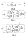
FIG. 5 is a diagram illustrating a method of channel estimation by complete correlation,
FIG. 6 is a block diagram illustrating a second method of channel estimation by alternating correlation, and
FIG. 7 is a block diagram illustrating a third method of channel estimation using a Golay correlator.
DETAILED DESCRIPTION OF THE PREFERRED EMBODIMENTS
A device intended to generate the composite sequence e(n) is presented in FIG. 3. It implements the principle of time multiplexing two complementary sequences s(n) and g(n). As will be understood, therefore, it corresponds to the relation (2) mentioned above.
The device of FIG. 3 comprises, connected in parallel, a first circuit 4 generating the sequence s(n), with n=0, . . . , N−1, a second circuit 5 generating the sequence Npg=0 and a third circuit 6 generating the sequence g(n), with n=0, . . . , N−1, the outputs of the generators being selectively connected to the output 7 of the device by a time multiplexing circuit 8.
The function of auto-correlation of the composite sequence obtained by this device can be written in the following manner:
Φe,e(n)=Φs,s(n)+Φg,g(n)+Φs,g(n−N−N pg)+Φg,s(n+N+N pg) (3)
One can see that it will be possible to obtain the estimation of the channel in a window of size 2·Npg+1 for which this auto-correlation function is equal to Φs,s(n)+Φg,g(n).
There will now follow a description of how the composite signal can be used to obtain an estimation of the channel, and in this connection several processes A, B and C will be described.
Estimation process A is based on a principle of complete correlation of the received signal with the composite sequence e(n), as FIG. 5 shows, by applying equation (3) above. In FIG. 5, the signal r(n) received in the receiver 2 is applied to the input of a correlator circuit 9 establishing a correlation between signal r(n) and signal e(n) of relation 2, the correlator 9 delivering at its output the estimation h(n) of the channel. The moment of reception of the composite sequence is assumed to be roughly known, which is necessary to synchronise the perfect estimation window of this estimation device. On the other hand, the impulse response is considered to be constant through all the composite sequence.
Estimation process B is based on a principle of partial and alternating correlation of the received signal with the sequences s(n) and g(n), as FIG. 6 shows.
In FIG. 6, the signal r(n) received in the receiver 2 is applied, on the one hand, to a first correlator 10, and, on the other hand, to a second correlator 11. Correlator 10 establishes the correlation of signal r(n) with sequence s(n) of relation (2), whilst the second correlator 11 establishes the correlation of signal r(n) with sequence g(n) of relation (2). The respective outputs of correlators 10 and 11 are connected to the mobile contacts 12 and 13 of a multiplexing device. Contact 12 is closed during the time interval N+Npg, contact 13 being open; contact 12 is open for the duration N+Npg, contact 13 being closed. Fixed contact 12 is connected to a circuit 14 with a delay d1 and fixed contact 13 is connected to a circuit 15 of delay d2. the outputs of circuits 14 and 15 are connected to the two inputs of an adder 16 which delivers the estimation h(n). The difference between delays d1 and d2 is equal to N+Npg.
This process makes it possible to suppress easily the inter-correlation components Φsgs(n)+Φg,s(n). In fact, the signals at the output of correlators 11 and 12 are respectively:
Φs,s(n)*h(n)+Φg,s(n−N−N pg)*h(n)
and
Φs,g(n)*h(n)+Φg,g(n−N−N pg)*h(n)
In taking into account, for a duration N+N
pg, only the output of the correlator by s(n), and then for a duration N+N
pg only the output of the correlator by g(n), only the signals Φ
s,s(n)*h(n) and Φ
g,g(n−N−N
pg)*h(n) are preserved. These signals are then delayed respectively by d
1 and d
2 bits and added, which gives finally at the output of the adder:
Which is the optimal estimation of the channel, with an offset shifted by close to d1 bits, d1 being known.
Process C consists in optimising the estimation process B from the point of view of the number of mathematical operations to be carried out, if the complementary sequences are constructed from polyphase complementary sequences, of which the Golay complementary sequences constitute the special case of a binary realisation. The correlations in relation to s(n) and in relation to g(n) can be realised in a single stage using a correlator optimised for polyphase complementary sequences and known under the name of Golay correlator (Extended Golay Correlator) which has been proposed in the literature. For this process C, the structure of the channel estimator then becomes that represented in FIG. 7.
The channel estimator of FIG. 7 comprises an input to which the signal r(n) received in the receiver 2 of FIG. 1 is applied. This input is connected, in parallel, to the two inputs of the Golay correlator 17 (EGC) which comprises two outputs selectively connected to the mobile contacts 18 and 19 of a multiplexing device. Contact 18 is closed during the time interval N+Npg, contact 19 being open; contact 18 is open for the duration N+Npg, contact 19 being closed. Fixed contact 18 is connected to a circuit 20 with a delay d1 and fixed contact 19 is connected to a circuit 21 of delay d2. The outputs of circuits 20 and 21 are connected to the two inputs of an adder 22 which delivers the estimation h(n). The difference between delays d1 and d2 is equal to N+Npg.